Understanding Orthographic Projection
One of the first steps in planning out and creating and drawing in Orthographic Projection is to decide on which views would best reflect the details and nature of the object, and to decide on a suitable Front View or Front Elevation.
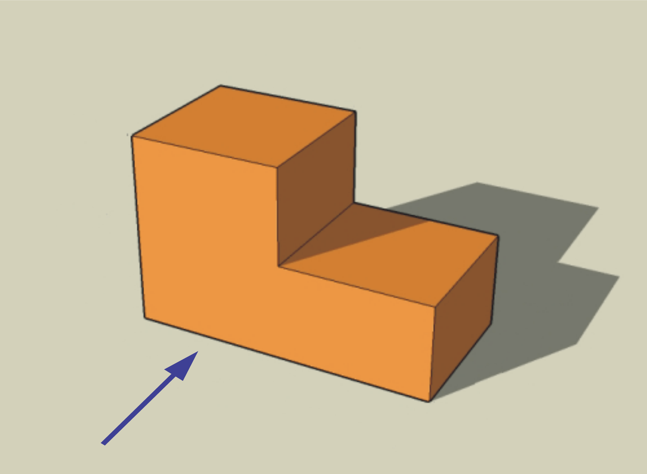
The Front Elevation should be the view that shows the most significant details of the object. For clarity, the object should be shown sitting in it's natural position. (i.e. not upside down)
Once you have established which views of the object you will draw, you need to visualize how each view will be placed on the sheet.
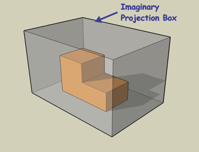
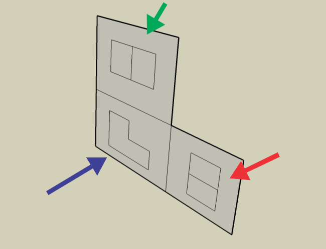
To create the individual views it sometimes helps to imagine the object being placed into a 'Projection Box'. This an imaginary box that will allow you to visualize how each surface will be 'projected' onto a flat sheet of paper, or in this case, a flat computer screen.
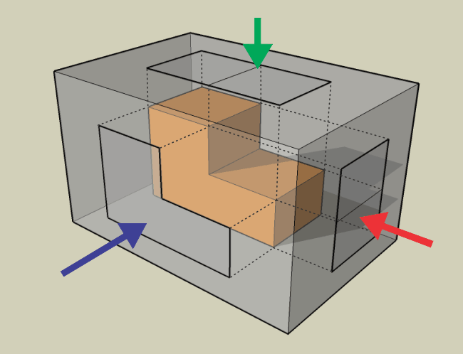
Visualize yourself standing perpendicular to each surface of the object that you will be drawing, and project each surface, edge, or detail out from the object onto the corresponding surface of the projection box.
Project each detail directly out, as you would see it if looking directly toward the surface of the object.
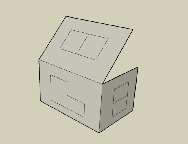
Visualize unfolding the box to flatten it out.
Here is the Orthographic Projection of the Top View, Front View, and Right Side View of the object. Now it is just a matter of establishing how and where you will line up and locate these views on your workspace.
The Spaces shown below are a rough approximation - NOT a scientific formula! You would use your judgment to produce a balanced and un-cluttered drawing.
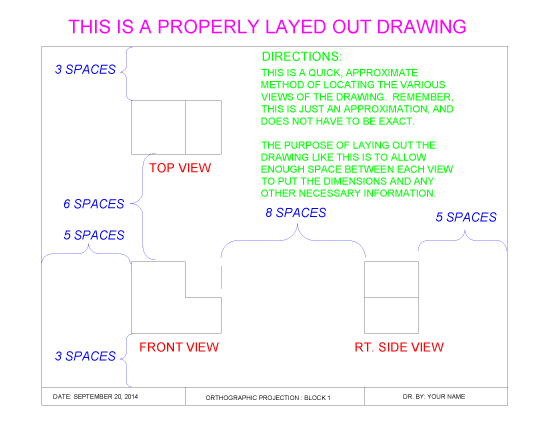
It may sometimes seem like a waste of paper, but you may need to leave room between the individual views for things like dimensions and notations. You also want your drawing to look balanced and un-cluttered.
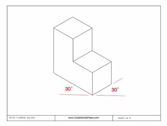
This is an exmple of an Isometric drawing. Is is a somewhat mechanical way of visualizing the object. Vertical lines are usually drawn vertically, but horizontal lines are drawn at either 30° or 45°. Although an isometric drawing can give the reader a reasonable idea of what the object looks like, it can be a bit confusing because it is not a natural visual of the object.
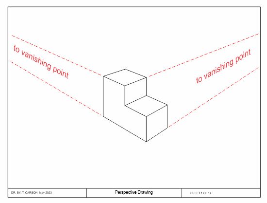
A perspective drawing is a more realistic and natural representation. They can be e ither a single point, a two-point, or a three-point perspective based on the number of vanishing points. This is a two-point perspective, with horizontal lines converging at a vanishing point. A two-point perspective assumes that the viewer is standing immediately in front of the object. A three-point perspective would represent the viewer either looking down on, or up at the object.
Although more realistic looking, the perspective drawing does not do a good job of indicating accuracy of depth.
This has been a very brief overview on Orthographic Projection, but hopefully it will be of some help in using your ScaleModelPlans.com plan package. Our N, HO, OO and O scale plan packages include a full set of orthographic drawings dimensioned in Imperial measurements, but since they are actual size you can take measurements directly from the printed sheets if you prefer to work in metric. Some isometric and perspective images are included where extra explanation might be helpful. Also included in our N, HO, OO, and O plan packages are actual size traceable templates that can be cut out and traced directly onto your building material. This is particularly handy for what could otherwise be complicated roof panels. Lastly, unless otherwise mentioned in our catalog description, scale plans will include a free printable cardstock version.
Thank you for visiting ScaleModelPlans.com and ScaleModelBuildings.com
© 2024 T. Carson